Posts

Showing posts from November, 2021

Exploring Solar Power - Where do I begin?

Image
I've got a new shed... And even though it's wired for power, my 16x9m shed is going to be powered as much as possible from solar panels and batteries.  Given that I have more than a few computers and radios in there, this is going to be a challenge. The house already has a set of panels and a big inverter, so this is really my own personal R&D project.  For safety, I am not attempting to connect my work to the house wiring, or feed into the grid.  I will be running separate wiring to power this gear. A note on safety Electricity is dangerous.  Contact with live wiring or components can be fatal.  I can't state this clearly enough, electric shocks can, and do kill people.  Batteries contain dangerous chemicals and can give off flammable gasses, which in a confined space can be explosive.  Connecting or disconnecting batteries can cause sparks, which could have very bad side effects. I will detail steps to mitigate these risks, but ultimately it is u...
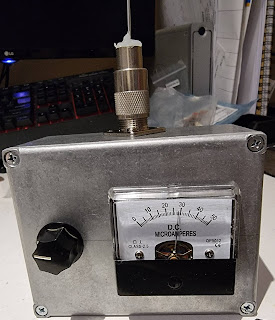
A No-Power Field Strength Meter

Image
    Before you scoff, this meter does work, and it works well.   Yet it has no battery, no amplifiers, transistors, valves, or even magical elves.   There are just 4 diodes and a capacitor inside the box, and if you have basic hand tools, should be able to make one in about an hour. The circuit is shown in figure 1, and it’s derived from my old RF Design textbook from the early 1980s.   A simple antenna is connected to the SO-239 connector.   A pair of diodes (D1 & D2 rectify the incoming voltage which charges C1.   The variable resistor, VR1 acts as a sensitivity control to allow you to take relative measurements.   Diodes D3 and D4 protect the meter from overloads. Construction There is no PCB or even board required.   D1 and D2 are connected directly to the SO-239.   C1 is soldered to the pins of VR1, while D3 and D4 are connected directly across the meter terminals.   To avoid short circuits, I covered D1 in heat shrink....