Posts

Showing posts from February, 2013

Forward To The Past - 6

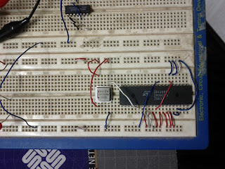
How are we going to power this thing? To start with, I have been using a bench power supply.  This is a very nice device, but not a good long-term solution. When the project is finished, I will most likely use a Jaycar MP3486 5V regulated plugpack .  These devices retail for around $A20 I don't think it's worth even designing a power supply.  We need only a single 5V rail and this supply has a 1.5A capacity which should be sufficient. If it's not enough, there is the MP3480 with a 3A rating. You might need to be a little forceful to use the latter with a breadboard however, because of the wire gauge.

Forward To The Past - 5

Image
Single Stepping So far, there's no reason why things should not just work.  But what if there's a problem?  Last night I was trying to work out why one of my address outputs didn't work right, and it occurred to me that since the Z80 is essentially a static processor, it would be pretty easy to add a single-step clock to our design so far. All this requires is a 74LS00 a Single-Pole Double-Throw (SPST) pushbutton switch and a couple of resistors.  Now, for each push of the switch we get one clock transition.  I will update the main schematic soon to reflect this change, and provide a way of selecting either option without rewiring, but since I'm working on breadboards, this is not too big a challenge to change over at the moment. Another option would be to use a very low speed clock.  We could either have a separate RC oscillator, or divide down the 8MHz signal to pretty much anything we like. What would you rather see?

Forward To The Past - 4

Image
Well Buffer Me... Having got our CPU up and running (sort of), the next step is to complete most of the core circuitry around the CPU. Historically, microprocessors were pretty fragile devices, and had a very limited fanout capability. That is, the ability to drive a number of integrated circuit inputs from it's output pins.  The solution is to add a driver or "buffer" device between the CPU and anything it needs to talk to. I will concede it isn't strictly necessary in our design but since I don't know what I am going to be connecting this device to in the future, better to start with a solid foundation. Right? One, Zero and Huh? But it gets a little more complicated, and I think we need to dive into some theory.  If you're an old hand feel free to skip ahead. Still here?  Good... We know there are two logic states High and Low (or 1 and 0 if you prefer) and we also know that multiple devices can't share the same wire in a simple circuit bec

Forward To The Past - 3

Image
One tiny victory tonight: If you tie all the data lines of a Z80 CPU low, then tie RST, BUSREQ, WAIT, INT and NMI high and apply a clock you get a rather large 16-bit counter.  Using an oscilloscope or even a fast logic probe, you will see the address lines cycling through Why?  Well opcode 00 is NOP (No Operation), so the address counter just moves on to the next address.  Other useful signs of life will be: /MREQ and /RD will be low (we're reading memory) while /IOREQ and /WR will be high.  HLT will also be high. I would also recommend using a packaged crystal oscillator, as it's just one less thing to have to get working. So for our first test, the wiring will be: Pin  Signal  Tie-to 16   /INT         +5 17  /NMI         +5 24  /WAIT      +5 25  /BUSREQ +5 26  /RST          +5   7  D4              GND   8  D3              GND   9  D5              GND 10  D6              GND 12  D2              GND 13  D7              GND 14  D0              GND 15

Foward to the past - 2

Foward to the past - 2 Almost everything arrived just moments ago from Element 14 .  By "almost everything", the only thing missing is the Z85C300 SIO chip.  But I can make a start without it I hope.

Foward to the past

OK, I admit it I am a bit old when it comes to the technology business.  I built my first "computer" such that it was in 1977 when I was thirteen years old.  I still have it in a box someplace too. So this started out as an exercise to show my kids (whom I love dearly, but see computers simply as commodities) just what is involved.  Before you all think I am a complete sadist one is studying mechatronic engineering, and another wants to work in IT when he finishes school.  (There's also an architect and a three year old who wants to be a doctor, but I digress) The plan was pretty simple.  Build a functional Z80 system from scratch.  Simple in principle, and hopefully execution as well.  When I mapped out the task I came up with the following: Create a simple design, based on datasheets.  Processor, RAM, ROM, Serial and Parallel I/O Get all the parts together Assemble it on a set of breadboards Write a simple monitor ROM Find something meaningful for it to do when