Forward To The Past - 4
Well Buffer Me...
Having got our CPU up and running (sort of), the next step is to complete most of the core circuitry around the CPU.Historically, microprocessors were pretty fragile devices, and had a very limited fanout capability. That is, the ability to drive a number of integrated circuit inputs from it's output pins. The solution is to add a driver or "buffer" device between the CPU and anything it needs to talk to.
I will concede it isn't strictly necessary in our design but since I don't know what I am going to be connecting this device to in the future, better to start with a solid foundation. Right?
One, Zero and Huh?
But it gets a little more complicated, and I think we need to dive into some theory. If you're an old hand feel free to skip ahead.Still here? Good...
We know there are two logic states High and Low (or 1 and 0 if you prefer) and we also know that multiple devices can't share the same wire in a simple circuit because the High (+5V) and the Low (0V) would not coexist. But snce we will have memory (more than one chip) and I/O sharing the address and data lines, how are we going to do it?
The answer is known as "Tri-State Logic". In Tri-State mode, the output of the chip is effectively not connected to the pin. The reality is somewhat more complicated than that, but for our purposes we can run with this assumption.
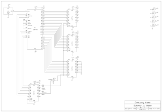
The last few paragraphs were a long-winded way of saying we need to use Tri-State buffer chips between the CPU and just about anything it wants to connect with. For the output lines (Address and Status) we will use three 74LS244 Octal Buffer devices. When the /ENABLE pins on these devices are High the outputs enter a Tri-State condition and the CPU is isolated from the bus.
One-Way Traffic
It's even more complicated yet however. The Address and Status lines from the microprocessor are straightforward, they are outputs. We can just buffer the signal and we're done. But the Data lines are more complicated, because they are bi-directional. These pins can be inputs or outputs. Fortunately, there is the 74LS245 Octal Transceiver. You could also use a pair of 74LS244's if you wanted, but you'd increase the complexity for no measurable gain.But how do you control it all?
So now we have everything buffered up, but how do we know when to turn buffer outputs on and off, or set the direction of a transceiver? The Z80 CPU does almost all of it for us. Overall output control is generated by using the /BUSACK signal. When a device wants to take control of the address and data busses, it will assert (drive Low) the /BUSREQ line. When the CPU is ready to grant control, it will assert /BUSACK. We can use /BUSACK to control the buffer devices in the following way. When /BUSACK is NOT asserted (High) we know the Z80 is in control and our buffers should be output enabled. But the /G line on the buffers needs to be Low to enable the outputs, so we use a 74LS04 inverter to reverse the signal for us.Similarly, when /DIR is asserted (driven Low), data flow from the "A" side of the 74LS245 to the "B" side. Since our "A" is connected to the Z80, /DIR means we are writing data. We can simply use the /WR line from the Z80 to achieve this.
Last Steps
We still don't have any memory yet (don't worry,we will get there!), so in order to test our work we will use the same trick as last time. Tie all the data lines Low. When you fire it up, you will see logic low on the CPU pins for the data and the buffered address lines will count out via the 74LS244'sParts List So Far
U1: Z80B CPUU2: 74LS244 Octal Buffer
U3: 74LS244 Octal Buffer
U4: 74LS245 Octal Transceiver
U5: 74LS04 Hex Inverter
U6: 74LS244 Octal Buffer
O1: 6MHZ Oscillator
C1: 0.1uF/10VW ceramic or monolithic capacitor
C2: 0.1uF/10VW ceramic or monolithic capacitor
C3: 0.1uF/10VW ceramic or monolithic capacitor
C4: 0.1uF/10VW ceramic or monolithic capacitor
C5: 0.1uF/10VW ceramic or monolithic capacitor


Comments
Post a Comment