Posts

Showing posts with the label Arduino

1200W HF Linear Amplifier from budget parts - 2

Image
While I'm waiting for the rest of the parts to turn up, I have started working out how to automate band-switching on the Low-Pass Filter module.  To do this, I am relying on the output of my IC-7300 transceiver to control this. If you want to skip ahead, the source code is located on my GitHub page:   https://github.com/au-chrismor/arduino7300 As noted in part 1 of this series , the IC-7300 outputs a voltage from 0 - 8V depending on the band selected.  The approximate values (from IC-7300 forums) are listed below: 630m     7.41V 160m     7.41V 80m        6.07V 60m        5.07V 40m        5.07V 30m        0.03V 20m        4.07V 17m        3.18V 15m        3.18V 12m        2.22V 10m        2.22V 6m          1.88V   My LPF has switch...

1200W HF Linear Amplifier from budget parts - 1

Image
This is either going to go very well or very badly, and if I'm honest it's 50/50 right now... I was scrolling through AliExpress (who doesn't?) and I came across a listing for a 1.2KW 1.8-54MHz LDMOS amplifier for a little over $A100.  Of course for this, it doesn't include the BLF188 device ($A300 from DigiKey).   Unlike most of the other amp packages on these markets, this one is assembled except for the LDMOS device, so there's no trying to interpret the schematic only to find it has nothing to do with the PCB you have on hand.   It didn't take long and the module arrived at my local post office.  It's small, at less than 100mm x 100mm and it appears to be quite well made: My research also tells me that a multi-band Low Pass Filter is an excellent idea and fortunately the same vendor has a nice unit at about twice the price of the amplifier module.  It arrived in the same package:   At about 250mm x 200mm it's substantially bigger than the amplifier,...

Exploring Solar Power - Are sure the safety is on?

Image
    OK, so we are getting closer to reality here.  Since the last article , I have made some small changes, which helped things out. Firstly, I added a 1000uF/63V filter capacitor to the battery output.  This practically eliminated the serious "hunting" issue that caused the software to rapidly ramp PWM values up and down almost constantly. Next I added two relays to the control circuit. The first is a battery cutoff, which will disconnect the battery if it is above 15V or below 9V, as these would indicate some kind of fault has occurred. The other relay disconnects the solar panel on the same principal.  If either of these events occur, the LCD indicates the nature of the fault. In order for battery monitoring to work effectively, the voltage divider must be located between the relay and the battery .  This way the battery can be reconnected automatically when the fault clears.  I have elected NOT to do this on the solar panel side as an over-voltage...

Meerkat Evo

Image
Evoluzione delle specie Seems there's another Evolution 2020, so don't get confused I published the plans and instructions for the original Meerkat around 2 years ago, and in that time Meerkat has done a lot of teaching work, not to mention being built quite a few times from my instructions. But over the last while he's been sitting there not doing much because of what I thought was a dead motor, and because my day job needs full attention.  But not that long ago, I got inspired to give Meerkat a proper update. In automotive parlance, this new version is an update of the existing model rather than an all-new model.  So I've decided to call the update " Meerkat Evoluzione 2020 " Back in the workshop again... So what is the feature list for the reborn 'Kat?  How is this for a start? Cliff detection.  Stairs are the enemy of most robots, so we'd better find them before we fall off. Power monitoring.  So Meerkat knows how much ...

WiFi Tank Robot in about an hour

Image
 (Left to Right, Auric and Oddjob) If you've been reading here for a while, you will probably remember Auric my large quad-track robot.  If not, you can read all about it here . Auric is still developing and getting smarter, but it's also really an expensive project.  I wanted something fun for the kids.  It had to be easy to build and able to handle indoor and outdoor conditions well. The solution came in the form of a "Black Gladiator" chassis from DF Robot .  Mine came from Little Bird Electronics in Hornsby New South Wales, for the princely sum of $A50. What I really like about this chassis is that unlike quite a few "budget" tracked chassis I have seen, this has an aluminum base plate which makes it not only stronger, but it shouldn't flex so much and cause damage to PCBs attached to it. It's a kit so you will need a small phillips-head screwdriver, soldering iron, cutters and medium duty hook-up wire.  When I received mi...

A "Proper" Robot

Image
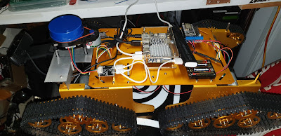
It seems to be that this time each year I introduce a new project, and 2019 not going to be any exception. My projects have become increasingly complex in recent years, and whilst I am still spending a lot of time on autonomous vehicles, according to feedback I have received, it is time to launch something that most enthusiasts could build if they wish. So, what does the list of requirements look like this time?  I am still drawing this one up, so as usual, you can follow the build and watch it evolve.  For now, here is what I have decided: The finished cost needs to be less that $A300.  Before you groan and say that it's way too expensive, Auric cost about eight times that amount, and is still not done.  I'm going to use off-the-shelf parts, especially from those low-cost marketplaces.  You can use upscale parts if you want, but you don't need to. Use a Raspberry Pi as the controller, and integrate all motion control.  The code for the autonomou...

Auric: Learning from testing

Image
It's amazing what you learn when testing in the real world... Auric went out for a long drive last weekend, while things went pretty well, there are always things to learn: 1.  Solving a performance problem Halfway through the long test I noticed that Auric was pulling to the left, and I suspected a motor drive problem.  After putting the machine up on a bench for a closer look I noticed something, well, "green" Upon closer inspection, Auric had decided to become an autonomous lawn mower and managed to wrap a 60cm grass runner around the front left drive.  Side effect was that the motor was loaded down and that caused thermal protection in the driver board to kick in. The final insult was when the imaging detected off-course behaviour and resulted in the motion controller trying to drive the jammed motor even harder, resulting in a vicious cycle. The end result of all of this is twofold.  Firstly, removing said grass solved the problem, and I wish t...

Auric: All about batteries

Image
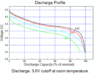
Batteries are really important if you're living off them OK, so this is going to be pretty boring, but it is important so bear with me. I learned from my experiments with the self-driving car that battery performance is critical, and to be honest last time I didn't pay enough attention.  I am making up for that oversight this time around. The Lovbio car used a 6V lead-acid battery to run it's motor.  Because that didn't give me too much headroom for my 5V powered electronics I had to run a separate 7.4V LiPo pack (commonly known as a "2S" pack) to run the electronics.  While it worked in the short term and helped the car to meet it's goals, it was not a viable solution . Because Auric is a ground-up design I had the opportunity to address a lot of the shortcomings from the last car and one of those was the power supply.  This time, it's a single battery and it's a big one, a 6200mAh 2S LiPo pack.  Basically it was the highest capacity...

Auric: An update

Image
I've been rather busy of late, and have not had as much time to spend on Auric as it has needed. The motor control has been a problem on this model right from the beginning, and I put some of it down to the L289 controller that is on the NodeMCU carrier.  I realise that this sounds like a poor workman blaming his tools, but early on, back-to-back testing showed the more common L298N-based drivers could drive the motors harder.  Packaging issues got in the way last time, and so I went with the NodeMCU and its carrier.  I paid the price in terms of performance. Unfortunately, there is still the packaging issue.  There are very few options for shields or carriers for a NodeMCU (to be honest, I can't find any other options), and there is simply not the space on Auric's deck for a separate driver module.  This may well mean changing out the controller altogether.  If I go to an Arduino UNO, such as I used the Self-Driving car, then I have a few more choices...

Auric - The Software Side

Auric is a combination of hardware and software. Last time we looked at the hardware required, and in this installment we will consider the software components. Like my previous self-driving car, there are two controllers in Auric.  The main processor and the motion control processor. Let's start with Motion Control because it is much simpler.   Motion Control is based on a NodeMCU (v1.0) and an associated L293D H-Bridge driver.  The software loop monitors the incoming serial port for a character stream from the main controller. This character stream is in the form of 'channel:value' .  These channel IDs are a single ASCII character (case-insensitive), and the value data is dependent on the channel.  For example R:512 is interpreted as Right Motor with a value of 512. It is the responsibility of the channel code to act and generate a response to the main processor. The main processor, a FriendlyARM NanoPC-T4 is primarily tasked with navigatio...

Introducing Auric

Image
Looks like something an evil genius should have, right? In my last update, I mentioned that the "Auric"* chassis was being used as part of my self-driving experiment.  Now it's time to unveil it properly. Auric is a T-900 tank chassis made by SZ-Doit .  It's not cheap, but you get a lot for your money: The chassis itself, in a choice of anodising colours Twenty (20) idler wheels Four driven wheels Plastic track Bearings Motors (9V with Hall-Effect sensors, or 12V without) 16550 Battery Holder (no batteries) Screws, Nuts. Washers Allen keys The only problem is that there are no instructions supplied.  SZ-Doit have a Wiki on GitHub, but for the most part you are referring to photographs of the finished product in order to assemble the machine. Also available is a motor shield which is used with a NodeMCU module.  Since this was featured in the company's build I added one of those as well. Auric is on YouTube now.  Click here to view ...