Introducing Auric
 |
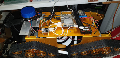
| Looks like something an evil genius should have, right? |
In my last update, I mentioned that the "Auric"* chassis was being used as part of my self-driving experiment. Now it's time to unveil it properly.
- The chassis itself, in a choice of anodising colours
- Twenty (20) idler wheels
- Four driven wheels
- Plastic track
- Bearings
- Motors (9V with Hall-Effect sensors, or 12V without)
- 16550 Battery Holder (no batteries)
- Screws, Nuts. Washers
- Allen keys
The only problem is that there are no instructions supplied. SZ-Doit have a Wiki on GitHub, but for the most part you are referring to photographs of the finished product in order to assemble the machine.
Also available is a motor shield which is used with a NodeMCU module. Since this was featured in the company's build I added one of those as well.
Some build notes
This thing is big! It is close to 50cm long and 30cm wide, so you need plenty of space when working on this chassis.
It's normal to have two idler wheels left over when building the quad-track version.
The motor wires are not long enough to reach the controller. I added a pair of terminal strips to the underside of the chassis, then connected from there to the controller.
Take your time lining up the drive wheel with the idler wheels. If they are not lined up well, there will be a tendency to throw tracks.
There are two ridges on the inside of the tracks. These go inside the the idler wheels. There is also a notch closer to one edge of the track. This faces out. If you keep these things in mind, lining up the track on the drive and idler wheels becomes easier to understand.
With the mechanical side done, I loaded the demo software onto the NodeMCU, and I could not get it to work, so I didn't bother with the BlueTooth control either. My GitHub repo contains a simple sketch that does work, and it would give you a starting point.
The shield uses an L293 driver which is different in operation to the Uno + L298 I usually run. One thing I noticed was the the motor speed is much lower on the NodeMCU + L293 driver, so you do need to take this into account.
 |
| Auric chatting with my Logic Analyser |
A Guided Tour
In a more-or-less central position is the new controller. I like the Raspberry Pi, but I these projects have simply outgrown their capabilities. After a lot of evaluation, I settled on the NanoPC-T4 from FriendlyArm.
 |
| Images courtesy of FriendlyElec/FriendlyArm |
This board uses a RockChip RK3389 SoC, it's still ARM, and runs Ubuntu. It's biggest advantages for me were the processor speed, and 4Gb of RAM. It also supports adding an NVMe storage device, but I have not enabled that just yet. There is also the usual WiFi (2.4/5G), BlueTooth, HDMI, etc. As a bonus, the 40-pin I/O header is pin-compatible with the Raspberry Pi.
At the rear of the chassis is a NodeMCU attached to an SZ-Doit Motor Shield. A simple serial connection (115200bps) connects the two devices together, and they use the same basic command/response protocol defined in my earlier self-driving experiments.
At the front are the two visually most interesting features. A forward-facing camera. You've seen this one before. It's connected to the T4 and drives the image-processing functions.
 |
| Long exposure shows the LIDAR in operation |
The blue cylinder is the X4 LIDAR unit from ydlidar. It generates 720 samples per rotation, thus 2 samples / degree, which is rather high resolution for an inexpensive device ($US99)
To mount the LIDAR and forward camera, I had to make a bracket from two back-to-back aluminium angle pieces.
LIDAR is great for knowing what is around you, but it is even more useful if you know were you are, and where you are going at the time. Two small modules make this possible. The first is an HMC5883L I2C Compass/Magnetometer module. This provides an heading record which is saved along with the LIDAR data.
Also included is a uBlox GPS receiver. This device is only for logging at this point, but in the future I want to us it for navigation as well.
All this hardware needs a considerable amount of power. The main processor needs 12V, which is a bit annoying.
Battery size and weight is always an issue with mobile devices, and Auric is no exception. Fortunately RC cars have faced similar problems, so I am presently using a 4C LiPo battery pack.
This provides 7.4V, so for 12V I used a small switch-mode regulator to run the NanoPC-T4. The motors are slightly under voltage, but I don't see this as a big issue for now, anyway.
 |
| Battery goes underneath |
That's enough of the hardware for now. In the next update, I will look at how the self-driving software was integrated into this platform, as well as how few changes were actually needed.
Want to help?
If you would like to make a financial contribution to the project, please go to my Patreon Page at:
*Auric gets it's name from Auric Goldfinger, a criminal genius obsessed with gold, in the James Bond novel and film "Goldfinger". Since the chassis was a golden colour, it just made sense at the time.


Comments
Post a Comment