Posts

1200W HF Linear Amplifier from budget parts - 2

Image
While I'm waiting for the rest of the parts to turn up, I have started working out how to automate band-switching on the Low-Pass Filter module.  To do this, I am relying on the output of my IC-7300 transceiver to control this. If you want to skip ahead, the source code is located on my GitHub page:   https://github.com/au-chrismor/arduino7300 As noted in part 1 of this series , the IC-7300 outputs a voltage from 0 - 8V depending on the band selected.  The approximate values (from IC-7300 forums) are listed below: 630m     7.41V 160m     7.41V 80m        6.07V 60m        5.07V 40m        5.07V 30m        0.03V 20m        4.07V 17m        3.18V 15m        3.18V 12m        2.22V 10m        2.22V 6m          1.88V   My LPF has switch inputs for: 10/12m 17/15m 30/20m 40m 80m Fortunately a lot of these will line up, at least for my usual bands. However there seems to be a bit of dispute about the actual voltages.  Icom don't publish anything, which is not entirely surprising.   My

1200W HF Linear Amplifier from budget parts - 1

Image
This is either going to go very well or very badly, and if I'm honest it's 50/50 right now... I was scrolling through AliExpress (who doesn't?) and I came across a listing for a 1.2KW 1.8-54MHz LDMOS amplifier for a little over $A100.  Of course for this, it doesn't include the BLF188 device ($A300 from DigiKey).   Unlike most of the other amp packages on these markets, this one is assembled except for the LDMOS device, so there's no trying to interpret the schematic only to find it has nothing to do with the PCB you have on hand.   It didn't take long and the module arrived at my local post office.  It's small, at less than 100mm x 100mm and it appears to be quite well made: My research also tells me that a multi-band Low Pass Filter is an excellent idea and fortunately the same vendor has a nice unit at about twice the price of the amplifier module.  It arrived in the same package:   At about 250mm x 200mm it's substantially bigger than the amplifier,

The IDPROM contents are invalid

Image
  I like my old Sun machines , but they have a small weakness in their design.  The older machines use a real-time clock known as an "IDPROM".  This device, originally made by Dallas Semiconductor has RAM, Clock, Crystal and a Battery all in one package.  If you read that back, you will see the problem: "Battery" The battery has a lifetime in years, but when it goes, the machine loses everything stored in the IDPROM.  The problem is that this data includes the MAC address, Host ID, Serial Number and even system type.  Without this data, your machine won't boot; and if it does, you won't have network access in all likelihood. Now, the chip is in a socket, because Sun knew it would fail and need replacement in the field, and while some devices (M48T02 and M48T58) are still available, other common devices, especially the M48T59 are no longer available, and there aren't and pin-compatible alternatives that I can find.   There are instructions online showing

ImageBuilder and Terraform - Handy Hints

This is for my benefit as much as anybody else, because it took me a while to figure things out: Most of the time when you write for AWS ImageBuilder, the docs tell you to create separate YAML files containing your components.  That's fine, but what if you want to do dynamic substitutions on path and file names?  In that case you probably want to do the definition in the HCL language.  That is, within the actual Terraform code itself. Using S3 One of the more fiddly bits is pulling things from S3 to install on your new instance.  You need to do two things: Have an IAM policy which allows access; and Write the component to do the job Writing the IAM Create a policy resource that looks something like this: resource "aws_iam_policy" "s3_policy" {     name = "s3-policy"     policy = jsonencode(       {           Version = "2012-10-17"           Statement = [             {               Effect = "Allow"               Action = [          

Exploring Solar Power - Are sure the safety is on?

Image
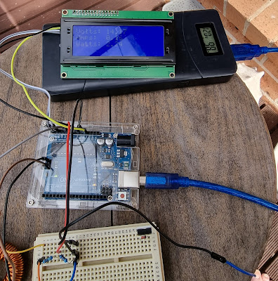
    OK, so we are getting closer to reality here.  Since the last article , I have made some small changes, which helped things out. Firstly, I added a 1000uF/63V filter capacitor to the battery output.  This practically eliminated the serious "hunting" issue that caused the software to rapidly ramp PWM values up and down almost constantly. Next I added two relays to the control circuit. The first is a battery cutoff, which will disconnect the battery if it is above 15V or below 9V, as these would indicate some kind of fault has occurred. The other relay disconnects the solar panel on the same principal.  If either of these events occur, the LCD indicates the nature of the fault. In order for battery monitoring to work effectively, the voltage divider must be located between the relay and the battery .  This way the battery can be reconnected automatically when the fault clears.  I have elected NOT to do this on the solar panel side as an over-voltage condition probably mean

Exploring Solar Power - Let there be smoke!

Image
Last time I introduced my new solar power project.  By the end of that post we were monitoring the power flow from the solar panel to the battery in a simple test environment.  This time we're going to dive in and start trying to control the charge power. What's MPPT? Maximum Power Point Tracking (or Transfer , depending on whom you ask) is a condition where we can transfer the highest power from the solar panel into the battery.  The key here is power, rather than voltage or current on their own.  Remember that power is the product of voltage and current, so it is possible that you will find that perhaps higher current and lower voltage (or vice versa) is the most efficient. What makes this a little problematic is that the peak power point varies constantly depending on the battery state of charge and temperature, so it is not a set and forget operation. This is why the first thing we did was to build a power monitor.  Now we can determine at any point of time, the power bein

Exploring Solar Power - Where do I begin?

Image
I've got a new shed... And even though it's wired for power, my 16x9m shed is going to be powered as much as possible from solar panels and batteries.  Given that I have more than a few computers and radios in there, this is going to be a challenge. The house already has a set of panels and a big inverter, so this is really my own personal R&D project.  For safety, I am not attempting to connect my work to the house wiring, or feed into the grid.  I will be running separate wiring to power this gear. A note on safety Electricity is dangerous.  Contact with live wiring or components can be fatal.  I can't state this clearly enough, electric shocks can, and do kill people.  Batteries contain dangerous chemicals and can give off flammable gasses, which in a confined space can be explosive.  Connecting or disconnecting batteries can cause sparks, which could have very bad side effects. I will detail steps to mitigate these risks, but ultimately it is up to you to be careful