Exploring Solar Power - Let there be smoke!
Last time I introduced my new solar power project. By the end of that post we were monitoring the power flow from the solar panel to the battery in a simple test environment. This time we're going to dive in and start trying to control the charge power.
What's MPPT?
Maximum Power Point Tracking (or Transfer, depending on whom you ask) is a condition where we can transfer the highest power from the solar panel into the battery. The key here is power, rather than voltage or current on their own. Remember that power is the product of voltage and current, so it is possible that you will find that perhaps higher current and lower voltage (or vice versa) is the most efficient.
What makes this a little problematic is that the peak power point varies constantly depending on the battery state of charge and temperature, so it is not a set and forget operation.
This is why the first thing we did was to build a power monitor. Now we can determine at any point of time, the power being supplied to the battery. But how do we control it?
We can control the output power using Pulse-Width Modulation or "PWM". This is exactly the same process as we would use to control the speed of a DC motor using this same controller. In simple terms we turn the power on and off rapidly, and we vary the duty cycle (on/off time). We then use a filter section to smooth out the pulses.
So, in short if the power increases, we want to see if the voltage increased. If so, let's see if we can bring it up further by increasing the duty cycle of the output. That is, keeping the output on for longer. If the power increased but the voltage decreased, then the current must have risen. In this case we want to reduce the duty cycle.
This is shown more clearly in the flowchart:
Now we know what to do, the question is how to do it. The best solution is to use a MOSFET (Metal Oxide Semiconductor Field-Effect Transistor) because it's "ON" resistance (a small fraction of an ohm) is small enough to be negligible for our purposes.
Please note, this is a simplification given the low power levels involved in the prototype. In a full-scale system, the ON resistance is a big deal...
I had a small module which I thought I would try first. This is nothing more than an IRF540N on a PCB with some terminals and a LED. I connected the "signal" pin (actually the MOSFET Gate pin) to the PWM output, connected the solar panel to V+ and V- on the module, and the battery to Out+ and Out-.
This all seemed pretty logical, and when I added a line of code to my monitor program to set a 50% duty cycle, there was a loud pop and smoke rose from the MOSFET. This was most definitely not what I expected to happen.
It didn't take too long to figure out my problem. I blew up a perfectly good MOSFET because I was trying to switch the wrong polarity. I was using an N-Channel device when I needed a P-Channel. Let's try that again with the right device. This time I used an IRF4905, which is a 75A/55V P-Channel device
About a week later, my parts turned up. (What, you think I just have every component on hand? Nah, but I have lots of suppliers on speed dial)
The revised schematic looks like this:
We are also only using the R3/R4 divider at this stage. You can add the other divider, or leave it out for now.
The purpose of the divider is to make sure that the voltage being measured can't exceed the allowed input voltage on the microcontroller.
This circuit is a very basic Buck Converter, which is a form of Switch-Mode Power Supply. Essentially, if we switch the MOSFET on and off fast enough, we can control the flow of current into the battery, and thus control the power.
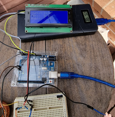
In order to see how this works, you can use a simple program on the Arduino which allows you to set the PWM duty cycle and measure the current using a multimeter. By using different duty cycles, you will achieve different current values.
Reloading the arduino with MPPT.ino, you will note a few things:
- The values "hunt" a lot. I think I need to build in some hysteresis on the controller rather than just letting it continually chase. More experimentation is required here.
- The MOSFET will get quite hot on a sunny day. Adding a small-ish TO-220 heatsink made a big difference, but I will consider adding temperature monitoring to the device as well, and probably a thermal shutdown.
While the circuit works, it is far from done. I need to boost the current-handling capability and add some filtering to the output. Over the next little while I intend to add a larger panel and battery to the system to better evaluate it's performance.
I am also considering replacing the Arduino with an ESP32 in order to get remote monitoring working.


Comments
Post a Comment