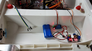
DIY Self-Driving - Part 3. Wiring Harnesses
Please Note: Unlike most of my projects which are fully complete before they are published, this project is as much a build diary as anything else. Whilst I am attempting to clearly document the processes, this is not a step-by-step guide, and later articles may well contradict earlier instructions.
If you decide you want to duplicate my build, please read through all the relevant articles before you start.
In the previous post we looked at getting a motor driver up and running, and I realised I breezed over the process of how it was all connected. This article will (hopefully) address that shortcoming.
Because this is a mobile project, vibration and the like will take a toll on connections and as we know, poor connections will lead to poor results. For this reason, I am going to take you through my process of making up wiring harnesses to suit our car. Clearly unless you are using the same car and modules as me your wiring is going to vary, but I hope this will get you headed in the right direction.
A bit about wire gauges
Even though this is relatively low power (for an electrical machine), we cannot use light-gauge hookup wire everywhere if we want to have a reliable result. So I have used three different gauges in this project:
17AWG - For the battery and motor connections. This is rated at around 8A.
nnAWG - for the 5V and lighting connections. Rated around 4A.
Rainbow hookup wire. I use this for control signals.
Proposed Wire Colours
You don't have to follow my scheme, but at least stick to whatever you do use. My colour coding is as follows:
- Red: Unregulated battery Voltage
- Black: Ground
- Orange: 5V regulated
- Blue: Head/Tail Lights
- Yellow: Indicators
Connectors
The basic electrics in my car are all connected with either bullet or spade connectors. You can get these from your friendly auto parts store or from an electronics retailer.
The controllers and sensor elements will need DuPont style connectors. I don't know how many I will need yet, but a pack of 500 is pretty cheap. Make sure you get both pin and socket types.
While you can terminate all of the above connectors with a pair of pliers, don't do it. Get a pair of crimpers. It will take less time and give you a better result.
If you wish to crimp and solder, be my guest.
Measure three times, cut once
Not much is going to be as frustrating as finding out that your beautifully-terminated cable is 1cm too short or twice as long as it needs to be. I find that using a length of scrap wire to plan out a run works well. Mark the length on that wire and cut your final cables against it. This way you can allow for any challenges in your path.
Secure your wiring
Next to the quality of connections in my opinion is making sure the wiring is safe and secure:
- Don't pull the cables tight, but keep them neat.
- Try to avoid attaching cables to things which move. If you must do this, allow for the movement, and sheath the cable to protect it.
- Anchor your wiring (those little self-adhesive mounts are great) to keep it out of harm's way
I recommend that you break your wiring into functional sections. This way you can test each element as you proceed. Some might argue it's not necessary, but I bell out (do a continuity check) on each cable before installation.
As you add each section, test it completely, or as completely as you can. Verify each function cable carries the voltage or signal you expect. Use a voltmeter as well, and check that you are getting the voltage you expected. If a cable is supposed to carry five volts, but you're seeing half of that then chances are there is a bad connection somewhere in the chain. By doing things in sections you can more easily backtrack to find the problem.
Finally, don't put problems off. If something is not working, or is intermittent at this early stage you can be sure it is going to cause you bigger issues as the car gets more complex. If you can't get your head around a problem by all means take a break or find some stickers for the body or something. But don't forget to come back and fix the problem before you go on to the next stage.
A note on safety
People will often dismiss safe practices when working on battery-powered equipment. When working on any kind of vehicle (or even a lot of flying models these days too) the batteries can deliver a very high current, especially with lithium-ion batteries.
While the power levels are not lethal in and of themselves, a short on a lithium battery, or the main battery for that matter can melt wiring and possibly start a fire. Just be careful as these cars are mostly plastic and therefore quite flammable.
 |
| Schematic diagram for stage 1 |
Further Reading
Part 1 - Introduction
Part 2 - Preparing the car
Part 4 - Steering
Part 5 - Sensors
Part 6 - Software
Part 7 - Final assembly and testing


Comments
Post a Comment