Build an obstacle-avoiding robot 1

These days they are also very inexpensive to get started with, thanks to Arduino and low-cost modules. Even if you don't know how to solder, chances are you could build the machine I describe here in an afternoon.
What is it?
It's been named "The Meerkat". If you watch the accompanying video it's not hard to see how the kids named it.
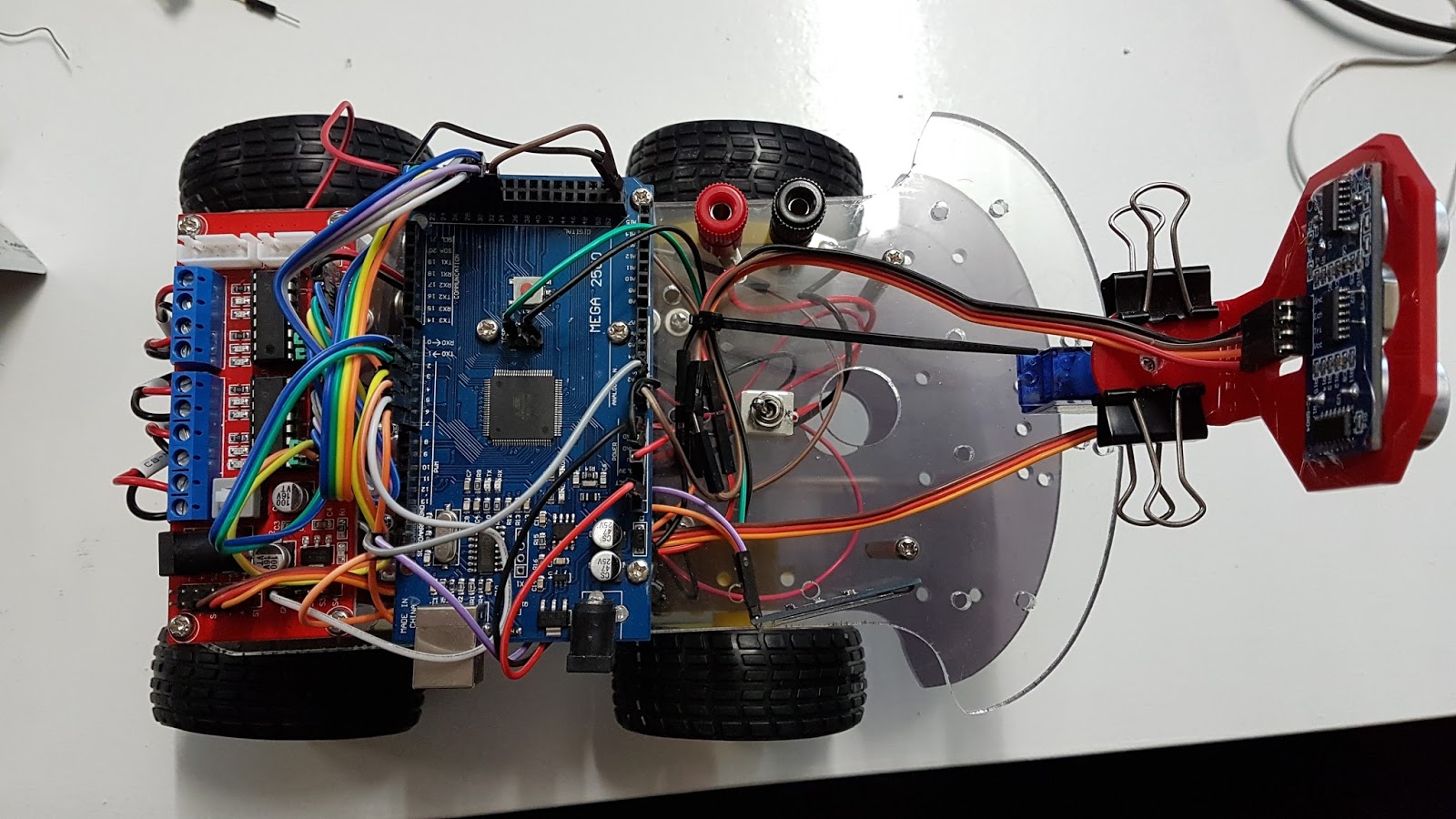
This is a 4-wheel machine which uses sonar to detect and avoid obstacles. To make life a little more interesting, the ultrasonic modules is steered using a small servo motor. This allows the machine to more effectively find a clear path.


The Design
At the heart of the robot is an Arduino Mega2560. This board has all of the I/O we need and is programmed with the Arduino IDE application.
The Arduino board cannot drive the motors by itself, the I/O ports cannot source or sink the necessary current. To solve this problem, we use an L298 H-Bridge driver module to drive the motors. Using an H-Bridge means we can reverse the polarity (and thus the direction) or a motor without needing relays. It also allows us to use Pulse-Width Modulation (PWM) to control the motor speed. So we need three control lines per motor. There are four motors to drive, so we need twelve connections and two motor driver chips.
At present the motors on each side only ever move in the same direction, and at the same speed. So you might wonder why not just use a two-channel driver. You could do this if you want to save a little money. But I wanted to build something a little more future-proof. These low-cost motors don't always run at the same speed, so we can do a calibration and store a speed offset in the EEPROM of the board for each motor. We could also vary the speed of motors to improve steering as well. We're not doing either of these today, but keep watching the code releases.
Obstacle direction is via a standard HC-SR04 ultrasonic rangefinder module under the control of the "NewPing" library. This is capable of quite fine resolution, and is more than adequate for our purpose. We want to detect an object within a few centimetres of the chassis.
Power comes from a pair of battery packs in parallel. If you use convention batteries, the 6-cell packs specified will supply 9 volts. If you go the rechargeable path, then they will supply 7.2 volts. Of course there is nothing to stop you from using lithium-ion or lithium-polymer batteries instead, however you need to make provision for charging those batteries as they have more complex requirements.
The parallel packs means plenty of current is available. Running four motors at normal speed requires around 180mA, so the extra capacity means plenty of run time at the cost of extra weight.
There is also the ability to add a small OLED display to the unit, as shown in the pictures. This is entirely optional but I found it very useful while I was debugging the software since it enabled me to see plainly what steps were executing.
There is also the ability to add a small OLED display to the unit, as shown in the pictures. This is entirely optional but I found it very useful while I was debugging the software since it enabled me to see plainly what steps were executing.
What will I need?
To get you started, you will need the following. Most of my parts came from Jaycar electronics and Altronics in Australia, but you can find much the same devices anywhere.
- 1 x 4WD Motor platform (Jaycar KR3162, Altronics K1092)
- Arduino Mega2560 (Various sources)
- 1 x 4-way L298 Motor Driver (Jaycar XC4460) or 2 x 2-way modules
- 2 x 6-cell AA Battery holders
- 1 x HC-SR04 Ultrasonic module
- 1 x small servo motor (Altronics Z6392)
- 1 x Bracket to suit ultrasonics
- 1 x DPDT switch
- Hook-up wire
- M3 screws and nuts (10-15mm)
- M3 spacers
- Heat Shrink tubing
- The source code
- Rechargeable batteries in place of standard AA-cells
- 2 x banana posts
- Zip ties
- SPI Compatible OLED Display (AdaFruit)
You're also going to need a PC or Mac with the Arduino software loaded, screwdrivers and a soldering iron. A hot-glue gun would also be useful.
Assuming you had to buy all the components, the total cost should be around 150 AUD. Not bad when you consider what it can do.
Assuming you had to buy all the components, the total cost should be around 150 AUD. Not bad when you consider what it can do.
Getting Started
The best place to start is with the chassis. There's a couple of useful things to consider when putting this together.
Motors and Wheels
If your motor have wires attached, it's almost certain that they will not be long enough to reach your driver board and you will need to extend them. My motor driver went on the top deck at the rear, as there were two holes located there already to take it. Solder and heat-shrink the connections.
Bolt your motors into place according to your platform. In same cases you can choose to put the motors above or below the bottom plate. I chose to put mine below because it frees up room for the battery packs, but it does make the finished product rather tall.
With a 3V battery, test each motor and determine the polarity which causes the motor to turn in a "forwards" direction. Label the leads as + and - according to the battery. This will make it easier when it comes to hooking up later.
Take some time now to properly align your wheels. Place a straight-edge (such as a metal rule) across the wheels on each side to and align them before finally tightening up the mounting screws. This might take a little time, but eliminating wheel drag improves battery life for free.
Mounting the modules
We have to mount the motor driver and Arduino Mega on the top deck. As noted before, the motor driver I used matched holes in the rear part of the top deck, so I put it there. The Arduino Mega needed new mounting holes, so work out and drill everything you need before you start assembling. While you're there drill a hole for the power switch and battery charging terminals if you're using them.
Mounting the ultrasonics and servo
This requires a little thought. Since only a tiny servo is required it doesn't take up much space, but at the same time this makes it tricky to mount since most commercial spacers won't clear the body of the servo. Because it's got so little mass on it I used industrial double-sided tape (the kind for sticking badges to cars) under the servo. Place it in the centre and running down the long axis of the chassis. (See photos)
Attaching the servo to the ultrasonic module requires a bracket of some kind. I made my own from acrylic. Turned out a bit on the large side but it works well. If you can find a long enough screw of the appropriate size just screw the bracket to the horn wheel on the servo.
Mounting the batteries
Make a design decision here. If you are using rechargeable batteries, you will need to add a connector for the charger (I used banana posts as per the photos), and the DPDT switch should isolate the electronics from the battery when charging for added protection.
However if you are using non-rechargeable batteries, make sure you have a way of getting at the battery holder(s) to change batteries without having to disassemble the whole machine. It might not look elegant, but a long cable (zip) tie is ideal for the job.
At this point, you should have everything mounted, but not wired. It looks pretty good for now, so let's move on to the wiring.
Wiring
The source code is the definitive guide to wiring the robot, and it will override any instructions here. All the information you require is in the file "rover_hw.h"
Motors
The motors are arranged as follows (looking from the top)
Back Right: Motor A
Back Left: Motor B
Front Right: Motor C
Front Left: Motor D
Some L298 driver boards jumper out the "Enable" pin for each motor channel. Refer to the documentation for your board and check if there is a jumper which needs to be removed.
The "A" and "B" (or "1" and "2") inputs on the motor driver control the direction.
The "A" and "B" (or "1" and "2") inputs on the motor driver control the direction.
Connections for the motor driver are as follows:
Motor A (1)
A => 22
B => 24
Enable => 2
Motor B (2)
A => 26
B => 28
Enable => 3
Motor C (3)
A => 30
B => 31
Enable => 4
Motor D (4)
A => 32
B => 33
Enable => 5 The motor driver board outputs are normally labelled "+" and "-". Connect the positive and negative leads from the motors to the outputs.

If you compile the code with "BURN_IN" defined, the software will cycle through each motor in turn. This is useful for checkout out the motor and servo wiring.
Servo
The motor driver I used also has a servo driver on-board so I used this to remove the load from the Arduino. However, the servo is small enough that it can be driven directly if required.
The servo needs +5V, Ground and Signal. The Signal comes from Output 6 on the Arduino. If your driver board supports servo motors, connect Output 6 to the control or signal input on the driver and connect the servo to the driver board instead.
Ultrasonics
The HC-SR04 needs +5V and Ground, as well as a Trigger. The detection result is returned via the Echo pin on the module.
Trigger is connected to pin 7, and Echo to pin 34.
Congratulations. Your robot is now fully assembled. If you wish, use some cable ties to make everything neat and secure.
The software
Like the rest of this project, the software is rather simple but you can still do a lot with it. First of all, grab the latest release from:Load up the Arduino IDE and open up "features.h". For now make sure that the line:
#define OLED
has been commented out. We will come back to that one later. If you want to test out your motor wiring, add the line:
#define BURN_IN
to "features.h"
But in either case, make sure the robot's wheels are clear of the ground before uploading the code.
Once you have confirmed that all the motors turn in the correct direction, removed the BURN_IN from the code and upload again.
Next Steps
I don't think any hobby robot is ever really "finished", and Meerkat certainly is proof of this. I have a lot of further plans for this little platform:- Wireless data transmission so we can tell what it's doing from afar.
- Navigation
- Battery Management
- Additional sensors for "experiments"


Comments
Post a Comment